DAIKIN ALARM LIST
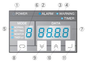
NO. | ITEM | DESCRIPTION |
1 | Power Lamp (Green) | The lamp is continuously on while power is supplied. |
2 | Error Warning Lamp (Red) | LEVEL 1 ALARM - Lamp keeps blinking |
LEVEL 2 ALARM - Lamp is continuously on | ||
3 | Warning Lamp (Green) | LEVEL 1 ALARM - Lamp keeps blinking |
LEVEL 2 ALARM - Lamp is continuously on | ||
4 | Timer Mode Lamp (Red) | The lamp keeps blinking while the machine is at the stop in the timer mode. |
5 | Operation Mode Display | NORMAL - Normal Mode |
MONITOR - Monitor Mode | ||
SETTING - Operation Setting Mode | ||
TIMER SET - Timer Setting Mode | ||
6 | Operation Mode/Data No. Display | Displays the current operation mode or data number of the data currently displayed on the data display. |
7 | Data Display | Displays various data. The data displayed differs depending on the operation mode and number. |
8 | Key | Selects the operation mode. |
9 | Key | Decrements the value of the operation mode, data number, or data by 1. When held for two seconds or longer, decrements the values by 10. |
10 | Key | Increments the value of the operation mode, data number, or data by 1. When held for two seconds or longer, increments the values by 10. |
11 | Confirm Key | Confirms the edited operation mode/data number/data |
Code | Malfunction | Condition |
A6 | DC fan stop. | Actual fan revolution falls below 10 rpm while in fan revolution. |
AA | Malfunction due to overheated heater. | For AKZ Series, the overheat prevention temperature switch reaches a temperature of 70°C. |
| ||
For AKZJ Series, the boil-dry prevention thermostat reaches a temperature of 105°C. | ||
E1 | System malfunction. | Compressor ID No. (PC board jumper setting). ? Parameter horsepower setting. |
E3 | Malfunction due to high pressure or condenser temperature. | The condenser temperature of 65°C or more continues for a period of 10 seconds. |
E5 | Malfunction due to discharge gas temperature or overheating compressor. | The discharge gas temperature exceeds A for a period of 10 seconds(*1). |
| ||
The compressor head temperature exceeds 115°C. | ||
E6 | Compressor lock at startup. | The compressor revolutions are not detected at startup. |
E9 | Malfunction of electronic expansion valve. | The malfunction is detected according to the EV valve opening and EV valve outlet temperature. |
EH | Actuation of pump overcurrent relay or actuation of agitator inner thermostat. | The pump current exceeds B(*2). |
EJ | Actuation of boil-dry prevention switch of actuation of optional safety devices. | The pressure reachers 0.03MPa (for -H units up to AKZ438/AKZJ458). |
| ||
The flow rate reaches 15 L/minute (for -H units up to AKZ568/AKZJ568). | ||
| ||
The safety device connected to X2M 12-13 activates. (Short-circuit). | ||
FE | Malfunction due to oil pressure (rise in pump outlet temperature). | The pump outlet temperature exceeds 65°C. |
FH | Rise in oil inlet temperature or rise in tank liquid temperature. | The oil inlet temperature exceeds 60°C for a period of consecutive 60 seconds. |
H1 | Malfunction of room temperature thermistor or malfunction of machine body synchronization thermistor. | The thermistor makes a short circuit or contains a broken wire. |
J3 | Malfunction of discharge has temperature thermistor. | The thermistor makes a short circuit or contains a broken wire. |
J5 | Malfunction of EV valve outlet temperature thermistor. | The thermistor makes a short circuit or contains a broken wire. |
J6 | Malfunction of condenser temperature thermistor. | The thermistor makes a short circuit or contains a broken wire. |
JE | Malfunction of pump outlet temperature thermistor. | The thermistor makes a short circuit or contains a broken wire. |
JH | Malfunction of outlet oil temperature thermistor or malfunction of inlet oil temperature thermistor. | The thermistor makes a short circuit or contains a broken wire. |
L0 | Malfunction of inverter/compressor. | Any of the malfunction codes L4, L5, L8, L9, and LA is displayed. |
L4 | Rise in radiation fin temperature. | The temperature rises to 95°C (up to 568 class) or 120°C (on 908 class). |
L5 | Instantaneous overcurrent of power transistor. | The output overcurrent is input int he microcomputer. |
L8 | Compressor overload. | The compressor output revolutions reach an abnormal level. |
L9 | Faulty compressor startup. | The compressor does not smoothly rotate at startup. |
LA | Malfunction of power transistor. | The microcomputer detects the malfunction of power transistor. |
LC | Malfunction of transmission between inverter CPU and temperature control CPU. | The transmission between the inverter microcomputer and the temperature control microcomputer malfunctions. |
P3 | Malfunction of control box thermistor. | The thermistor makes a short circuit or contains a broken wire. |
P4 | Malfunction of tin temperature thermistor. | The thermistor makes a short circuit or contains a broken wire. |
U0 | Shortage of refrigerant. | 1. Command capacity = 95%. |
| ||
2. Condenser temperature - EV valve outlet temperature = 5°C. | ||
| ||
1 and 2 continues for a period of three minutes. | ||
U1 | Reverse phase/open phase of power supply or wire broken in fuse. | Reverse phase or open phase is detected in power supply circuit. |
U2 | Malfunction due to power supply voltage. | The power supply voltage drops below 170 V. |
U9 | Malfunction of transmission with slave unit. | While in pair operation of master and slave units, data transmission with other systems. |
UH | System-related failure. | EEPROM causes a failure. |
UJ | Actuation of external safety device. | A short circuit occurs between the terminals of CN2 on the main PC board. |